Manuals

sennheiser tr 175 manual

Sennheiser TR 175 Manual⁚ A Comprehensive Guide

This manual provides a complete guide to using your Sennheiser TR 175 digital wireless headphone system. It covers setup, connection, troubleshooting, and maintenance, ensuring optimal sound and longevity. Downloadable PDFs offer additional support.

The Sennheiser TR 175 represents a significant advancement in digital wireless headphone technology, designed to deliver an unparalleled audio experience. This system seamlessly integrates sophisticated digital transmission with comfortable, high-fidelity headphones, making it ideal for a wide range of applications. Whether you’re immersing yourself in the captivating soundscapes of your favorite movies, enjoying the nuances of your music collection, or simply seeking crystal-clear audio during television viewing, the TR 175 is engineered to meet your needs.

Its intuitive design and user-friendly interface make setup and operation a breeze, allowing you to focus on what truly matters⁚ the exceptional audio quality. The TR 175 system boasts a robust range, ensuring a stable and uninterrupted connection even in larger rooms or homes. This comprehensive manual will guide you step-by-step through the setup process, explaining each feature and function in detail, empowering you to fully harness the potential of your Sennheiser TR 175 system. From connecting the transmitter and headphones to optimizing the sound settings and troubleshooting potential issues, this guide ensures a seamless and enjoyable user experience.

Key Features and Specifications

The Sennheiser TR 175 boasts several key features designed for superior audio performance and user convenience. These include closed, circumaural headphones ensuring excellent noise isolation and immersive sound. Digital wireless transmission provides exceptional audio clarity and a wide transmission range, minimizing signal interference and dropouts. The system also offers customizable sound profiles, allowing users to switch between dynamic bass and virtual surround sound modes to optimize the listening experience based on their preference and the content being enjoyed. This adaptability enhances the versatility of the TR 175, making it suitable for a wide range of audio applications.

Specific technical details may vary depending on the exact model and region. However, expect a robust wireless range (often cited as up to 100 meters line of sight), along with the ability to connect to various audio sources via optical digital input. While the manual may not explicitly list battery type and life, it is essential to consult the included documentation or the Sennheiser website for precise specifications on battery requirements, compatibility and expected operational duration. Always refer to the official documentation for the most up-to-date and accurate technical specifications concerning your individual unit.

Connecting the Transmitter and Headphones

Establishing a connection between the Sennheiser TR 175 transmitter and headphones is typically straightforward. Begin by ensuring both devices are powered on. The transmitter usually requires a connection to your audio source, often achieved via an optical digital cable. Connect one end of this cable to the “DIGITAL OPTICAL IN” input on the transmitter and the other end to the corresponding optical output on your audio source (such as a television or audio receiver). It’s crucial to note that some TV models may automatically mute their internal speakers when an external device is connected to the headphone jack. Consult your TV’s manual if you encounter this issue.

Once the transmitter is connected to your audio source, the headphones should automatically pair with the transmitter. If not, refer to the specific instructions within your user manual for pairing procedures, which may involve pressing a pairing button on either the transmitter or headphones. The manual may also provide troubleshooting steps if the connection fails. Remember to always check that the headphones are adequately charged before attempting to connect and operate the system. Correctly establishing this connection is crucial for optimal sound quality and reliable performance. If you encounter persistent connection problems, consider consulting Sennheiser’s online support resources or contacting their customer service.

Setting Up the System for Optimal Sound

Optimizing your Sennheiser TR 175 system for the best audio experience involves several key steps. Begin by ensuring the transmitter is correctly connected to your audio source, using a high-quality optical digital cable for the clearest signal. Then, carefully adjust the volume levels on both the transmitter and the headphones themselves. Avoid setting either too high, as this can lead to distortion or hearing damage. Experiment with the available sound modes, such as dynamic bass boost or virtual surround sound, to find the settings that best suit your preferences and the type of audio you’re listening to. These modes often provide customized sound profiles for different listening environments and content.

The placement of the transmitter is also crucial for optimal wireless performance. Keep the transmitter within a reasonable distance from the headphones, minimizing obstructions between them for the strongest signal. Avoid placing the transmitter near electronic devices that might cause interference. If you’re still not satisfied with the sound quality, explore the advanced audio settings available in your system’s menu, if applicable. These settings might include equalization (EQ) adjustments or other fine-tuning options to tailor the sound to your specific taste and listening environment. Remember to consult the user manual for detailed information on the various sound customization options your specific model offers.

Troubleshooting Common Issues

If you encounter problems with your Sennheiser TR 175 system, this section offers solutions to common issues. First, check the batteries in both the transmitter and headphones. Low battery power can lead to poor audio quality or complete system failure. Replace with fresh batteries if necessary. Next, ensure all connections are secure. Double-check the optical digital cable connection between the transmitter and your audio source, ensuring it’s firmly plugged in on both ends. If using an alternative connection method, verify that it’s correctly established as per the device’s instructions.
If the audio is distorted or crackling, try moving the transmitter further away from potential sources of wireless interference, such as other electronic devices or Wi-Fi routers. Experiment with different locations for the transmitter to pinpoint interference sources. If you’re experiencing a weak signal or dropouts, ensure there are minimal obstructions between the transmitter and the headphones. Walls, furniture, and other objects can impede the wireless signal. For persistent issues, consult the online resources or contact Sennheiser’s customer support. They can provide tailored assistance based on your specific model and setup.

Battery Information and Replacement

The Sennheiser TR 175 system utilizes readily available batteries for both the transmitter and the headphones. The headphones typically employ standard AAA batteries. You have the flexibility to use either regular alkaline batteries for single-use applications or rechargeable NiMH AAA batteries for extended use and environmental friendliness. Always ensure that you use batteries of the correct size and type as specified in the accompanying documentation. Using incorrect batteries can damage the device and void any warranty.

To replace the batteries in your headphones, carefully open the battery compartment, usually located on the side or underside of the earcup. Once open, remove the depleted batteries and insert new ones, paying close attention to the correct polarity (+ and -). Incorrect polarity can damage the battery compartment and the internal circuitry. Refer to the diagram inside the battery compartment for correct polarity if necessary. After replacing the batteries, close the compartment securely. For the transmitter’s battery, consult the specific instructions provided with your model, as battery types and replacement procedures may vary.

Remember to dispose of used batteries responsibly, following local environmental regulations. Avoid throwing batteries in household trash. Proper disposal protects the environment and prevents potential hazards. Regularly check the battery levels to ensure uninterrupted listening pleasure.

Cleaning and Maintenance

Regular cleaning of your Sennheiser TR 175 headphones and transmitter is essential to maintain optimal performance and extend their lifespan. Avoid using harsh chemicals, abrasive cleaners, or excessive moisture, which can damage the surface finishes and internal components. For cleaning the earcups and headband, use a soft, slightly damp cloth. Gently wipe away any dirt or debris. For stubborn stains, consider using a mild soap solution, ensuring the cloth is only slightly damp to avoid getting moisture inside the headphones. Allow the headphones to air dry completely before use. Never immerse the headphones or transmitter in water or any other liquid.

The transmitter unit should be cleaned with a similar approach. Use a soft, dry cloth to wipe away dust and fingerprints. If necessary, use a slightly damp cloth for more stubborn marks. Again, ensure the cloth is not overly wet. Avoid spraying any cleaning solutions directly onto the transmitter. For optimal performance and hygiene, regularly clean the earcups, particularly if sharing the headphones. This prevents the buildup of sweat, oil, and other contaminants that could affect sound quality and hygiene.

Store your Sennheiser TR 175 system in a cool, dry place, away from direct sunlight and extreme temperatures. Avoid storing the headphones under pressure or in a confined space, which could damage the earcups or headband. Proper storage contributes to extended product life and prevents accidental damage.

Safety Precautions and Warnings

To ensure safe and proper use of your Sennheiser TR 175 wireless headphone system, please adhere to the following safety precautions. Never use the headphones at excessively high volume levels, as this can cause permanent hearing damage. Gradually increase the volume to a comfortable level to protect your hearing. Prolonged exposure to loud sounds can lead to hearing loss, so be mindful of the volume levels, especially over extended periods. Avoid using the headphones in environments where hearing protection is recommended, such as noisy construction sites or industrial settings.

Keep the headphones and transmitter away from water and other liquids. Do not immerse them in water or expose them to excessive moisture, as this can cause damage to the electronics. If any liquid spills onto the device, immediately disconnect it from the power source and allow it to dry completely before using again. Never attempt to repair the headphones or transmitter yourself. If any problems arise, contact Sennheiser customer support or an authorized service center.

Do not use the headphones near heat sources, such as fireplaces or heaters, as this can damage the electronics and potentially pose a fire hazard. Handle the headphones with care and avoid dropping them or subjecting them to significant impacts. Keep the headphones away from small children to prevent accidental damage or injury. Regularly inspect the headphones and transmitter for any signs of damage or wear and tear and discontinue use if any issues are found.

Understanding the Controls and Functions

The Sennheiser TR 175 boasts an intuitive control layout for seamless operation. The transmitter unit typically features a power switch, volume control knob, and potentially a mode selector for switching between different audio modes (e.g., stereo, mono). Familiarize yourself with the positions and functions of each control. The volume knob allows you to adjust the audio output level to your preference. Ensure that the volume is set to a safe listening level to avoid potential hearing damage. The power switch turns the transmitter on and off, conserving battery life when not in use. The mode selector, if present, enables you to customize your listening experience based on your needs.

The headphones themselves may include additional controls. Some models incorporate buttons or a dial for adjusting volume directly on the headphones, offering convenient adjustments without needing to interact with the transmitter. Others may have a power switch integrated into the earcup. Check your specific model’s instructions for the exact control layout and their associated functions. Understanding these controls will ensure you can easily manage your audio experience and customize the sound settings to meet your personal preferences.

Before operating, carefully review the included diagrams and illustrations to identify all controls and their purposes. This understanding will allow you to fully utilize the features of the Sennheiser TR 175 system and achieve the best possible listening experience.

Digital Wireless Technology Explained

The Sennheiser TR 175 utilizes digital wireless technology for superior audio transmission. Unlike analog systems, which are susceptible to interference and signal degradation, digital transmission offers significant advantages. Digital signals are less prone to noise and distortion, resulting in clearer, more accurate sound reproduction. The digital signal is encoded and then transmitted wirelessly to the headphones, significantly reducing the impact of environmental interference. This results in a more consistent and high-fidelity listening experience.

This technology provides several key benefits. The extended range minimizes dropouts and interruptions, particularly useful in larger rooms. The digital signal processing enhances audio quality, delivering richer, more detailed sound. Furthermore, the digital signal is more resistant to interference from other electronic devices; The use of digital wireless technology ensures a more stable and reliable connection compared to older analog systems, leading to a superior listening experience with fewer interruptions and improved audio quality. This robustness is crucial for enjoying uninterrupted audio playback. The enhanced clarity and reduced distortion contribute to a more immersive and engaging listening experience.

The specific digital encoding and transmission methods used in the Sennheiser TR 175 may vary, but the core benefit remains consistent⁚ high-quality, reliable wireless audio transmission.

Accessing Online Resources and Support

Sennheiser provides comprehensive online resources to assist users with their TR 175 headphones. Their website, often cited as www.sennheiser.com, is a primary source of information. Here, users can download the complete instruction manual in PDF format, available in multiple languages. This manual offers detailed instructions for setup, operation, and troubleshooting common issues. Beyond the manual, the website may also host FAQs (Frequently Asked Questions) addressing common user queries. These FAQs can provide quick answers to simple questions without the need to search through the extensive manual.

In addition to the website, Sennheiser may offer online forums or communities where users can interact with each other and Sennheiser support staff. These forums are valuable for sharing experiences, tips, and troubleshooting solutions. Users can post questions, receive assistance from other users, and potentially find solutions to problems not explicitly addressed in the manual. Contacting Sennheiser directly through their website or phone support may also be an option for more complex issues requiring direct assistance from their technical team. The contact information is typically readily available on their website. Remember to have your product’s serial number ready when seeking support.

Utilizing these online resources ensures users can readily access the support and information needed to fully utilize their Sennheiser TR 175 headphones.

Additional Accessories and Compatibility

While the Sennheiser TR 175 is designed as a standalone digital wireless headphone system, the possibility of additional accessories and compatibility with other devices should be considered. The provided text mentions the inclusion of an instruction manual within a charging case (EZL 2020-20 L), suggesting potential accessory bundles or future compatible charging solutions. However, specific details regarding other compatible accessories are not explicitly stated within the provided text.

Regarding compatibility, the system’s connection to various audio sources is a key factor. The text highlights the use of an optical digital cable to connect the transmitter to audio sources like televisions. This implies compatibility with devices possessing an optical digital audio output. However, the potential compatibility with other audio devices, such as certain types of media players or computers, remains unclear. It is important to consult the full Sennheiser TR 175 instruction manual or the manufacturer’s website for a comprehensive list of compatible devices and any recommended additional accessories.

Checking for updates or new accessories through the Sennheiser website is advisable. They may release updated firmware or offer additional accessories that enhance the functionality of the TR 175 system over time. Always refer to the official Sennheiser resources for the most accurate and up-to-date information on compatibility and available accessories.

Manuals

dyson dc24 all floors manual

Dyson DC24⁚ Model Variations and Manuals

The Dyson DC24 boasts several model variations, including the Multi Floor, Multi Floor Complete, Animal, Multi Floor Exclusive, Drawing Limited Edition, Blitz It, Independent, and the standard DC24.

User manuals are readily available online in PDF format. Downloadable versions often include detailed diagrams and instructions for setup and maintenance.

While user manuals are easily accessible, dedicated service manuals may require contacting Dyson support or searching specialized repair websites.

Available Models

The Dyson DC24 vacuum cleaner was offered in a variety of models, each designed to cater to specific cleaning needs and preferences. Among the most common variations were the Dyson DC24 Multi Floor, a versatile model suitable for various floor types; the Dyson DC24 Multi Floor Complete, often bundled with additional accessories; and the Dyson DC24 Animal, specifically engineered for pet owners to tackle pet hair effectively. Other less common models included the Dyson DC24 Multi Floor Exclusive, potentially featuring unique design elements or added features, the Dyson DC24 Drawing Limited Edition, possibly a special release with a distinctive aesthetic, and the Dyson DC24 Blitz It, perhaps emphasizing speed and efficiency. Finally, there’s mention of a Dyson DC24 Independent model, although its precise specifications may require further research. These variations highlight Dyson’s commitment to providing tailored solutions for a broad range of consumer needs and preferences within the DC24 product line.

Accessing the User Manual

Locating the user manual for your Dyson DC24 is straightforward thanks to readily available online resources. Dyson’s official website provides a dedicated support section where you can easily search for and download the manual specific to your DC24 model. Simply navigate to their support page, input your model number (ensuring accuracy), and download the PDF version. The digital format allows for easy access, printing, and convenient storage. Alternatively, many third-party websites specializing in appliance manuals also host the Dyson DC24 manual, offering alternative download options if needed. These resources typically allow for searching by model number, making the process quick and efficient. Remember to verify the authenticity of the downloaded manual to ensure you’re accessing accurate and up-to-date information from a reputable source before using it.

Finding Service Manuals

Unlike readily available user manuals, obtaining a comprehensive Dyson DC24 service manual might require more effort. While Dyson’s official website offers user guides and troubleshooting tips, detailed service manuals containing intricate diagrams and technical specifications are generally not publicly accessible. These manuals are often reserved for authorized service centers and repair technicians due to the complexity of internal components and potential safety hazards. To access a service manual, contacting Dyson’s customer support directly may be necessary; they can guide you on repair options, potentially providing access to relevant information or directing you to an authorized repair center. Independent repair websites or forums might offer some service-related information, but exercise caution when using unofficial sources. Always prioritize official channels for accurate repair guidance to avoid damaging your vacuum cleaner.

Dyson DC24⁚ Operation and Maintenance

Always refer to the user manual for safe operation. Never use the vacuum with damaged cords or components. Regularly inspect and maintain filters.

Safe Operation Procedures

Before operating your Dyson DC24, carefully read the entire user manual. Ensure the power cord is undamaged and properly connected. Never operate the vacuum cleaner if the cord or plug shows signs of wear or damage. Always inspect the hose, wand, and brush bar for obstructions before each use, clearing any blockages to prevent motor strain and potential damage. During operation, maintain awareness of the vacuum’s cord to avoid tripping hazards. Do not use the vacuum cleaner near water or other liquids. Keep the vacuum cleaner away from children and pets during operation. Use only Dyson-recommended attachments and replacement parts to prevent malfunctions or safety hazards. Regularly empty the dustbin and clean or replace filters to maintain optimal suction and performance. Never attempt to repair the vacuum cleaner yourself unless explicitly outlined in the user manual. Contact Dyson customer support or authorized service centers for any repairs or maintenance outside your expertise. Following these guidelines ensures safe and effective use of your Dyson DC24.

Recommended Accessories and Parts

To maximize the cleaning performance and longevity of your Dyson DC24, use only Dyson-recommended accessories and replacement parts. Using non-Dyson parts can void your warranty and potentially damage your vacuum cleaner. Essential accessories often include various cleaning heads designed for different floor types (hard floors, carpets, etc.), crevice tools for reaching tight spaces, and upholstery tools for cleaning furniture. Regularly check the condition of your accessories and replace any worn or damaged components promptly. Dyson offers a range of replacement filters, crucial for maintaining optimal suction and preventing dust and allergens from escaping back into the air. For specific compatibility and ordering information, consult the Dyson website or contact customer support. Purchasing genuine Dyson parts ensures optimal performance, safety, and prolongs the lifespan of your vacuum cleaner, offering the best possible cleaning experience.

Maintenance and Troubleshooting

Regular maintenance is key to keeping your Dyson DC24 running smoothly. Empty the dustbin after each use to prevent clogging and maintain suction power. Wash the filters regularly, at least monthly, using cold water; allow them to dry completely before reinstalling. Check the brush bar for hair and debris tangles; remove obstructions to ensure optimal performance. Inspect the hose and wand for blockages that could restrict airflow and reduce suction. If you notice a decrease in suction, check the filters first, followed by the brush bar and hose. The user manual will provide detailed instructions on how to access and clean these components. For more complex issues, refer to the troubleshooting section in your manual or contact Dyson customer support. Addressing minor problems promptly can prevent major repairs and extend the lifespan of your vacuum cleaner. Remember to always unplug the vacuum before performing any maintenance.

Dyson DC24⁚ Troubleshooting Common Issues

A loud motor often indicates a blockage; check the hose, wand, and brush bar for obstructions.

Tangled hair or debris can hinder the brush bar’s function; remove any obstructions and inspect for damage.

Reduced suction usually stems from clogged filters or a full dustbin; check and clean these components.

Noisy Motor Operation

An unusually loud Dyson DC24 motor often signals a problem hindering airflow. This noise can manifest as a louder-than-normal hum, pulsing on and off, or even complete motor failure. The increased strain on the motor is a direct result of restricted airflow somewhere within the system. Begin troubleshooting by systematically checking for blockages. First, examine the dustbin; a full bin restricts airflow and forces the motor to work harder, leading to increased noise. Next, inspect the filters. Clogged filters severely impede airflow and can cause excessive motor noise. Remember to regularly clean or replace filters according to the manufacturer’s recommendations. After checking the bin and filters, thoroughly inspect the hose, wand, and brush bar for any obstructions such as tangled hair, string, or small debris that may be restricting airflow. If the noise persists after these checks, the problem might be more serious and require professional attention. A malfunctioning motor may need repair or replacement by a qualified technician. Always refer to the Dyson DC24 user manual for detailed instructions and safety precautions before attempting any repairs or maintenance.

Brush Bar Problems

The Dyson DC24 brush bar is crucial for effective cleaning, and malfunctions can significantly impact performance. A common issue is the brush bar becoming entangled with hair, string, or other debris, preventing it from rotating freely. This often leads to reduced suction and uneven cleaning. To address this, power off and unplug the vacuum cleaner before accessing the brush bar. Usually, you’ll need to unlock the soleplate using a coin or screwdriver, providing access to the brush bar. Carefully remove any obstructions, ensuring you clear all tangled material from the brush bar and its surrounding area. If the brush bar itself is damaged – perhaps bent or broken – it might require replacement. Refer to your Dyson DC24 user manual for guidance on accessing and replacing the brush bar. Inspect the brush bar regularly for wear and tear, paying attention to the bristles. Worn or damaged bristles reduce cleaning effectiveness. Again, the manual provides information on replacement parts and procedures. A non-rotating or poorly rotating brush bar can significantly reduce cleaning efficiency, warranting prompt attention and maintenance.

Suction Issues

Reduced suction in your Dyson DC24 can stem from several sources, often easily addressed with routine maintenance. Begin by checking the dustbin; a full bin restricts airflow, dramatically reducing suction. Empty the bin and clean the filters. Clogged filters are a frequent culprit, impeding airflow and diminishing cleaning power. Wash the filters according to the instructions in your user manual; allow them to dry completely before reinstalling. Inspect the hose and wand for blockages; obstructions can significantly impede suction. Carefully examine these components, removing any debris that may be lodged inside. The brush bar itself can also cause suction problems if it’s clogged or damaged, restricting airflow. Check for hair, string, or other debris wrapped around the brush bar. A malfunctioning brush bar might require cleaning or even replacement. If the problem persists after these checks, there could be a more serious internal issue requiring professional attention or Dyson support. Ensure the vacuum is properly assembled; loose or improperly connected components can affect airflow and suction.

Dyson DC24⁚ Additional Resources

Contact Dyson directly via phone or their website for troubleshooting assistance, parts, or repairs. Their support pages often provide helpful FAQs and videos.

Seek advice and solutions from other Dyson DC24 owners on online forums and communities dedicated to vacuum cleaner repair and maintenance.

Numerous online retailers specialize in Dyson parts, offering convenient access to replacement components when needed for self-repair.

Official Dyson Support

Dyson provides comprehensive support for its products, including the DC24. Their official website offers a wealth of resources, including downloadable user manuals in PDF format for various DC24 models (Multi Floor, Animal, etc.). These manuals often contain detailed diagrams, troubleshooting tips, and maintenance instructions. Beyond the website, Dyson maintains a customer service helpline, readily accessible via phone, allowing users to directly address specific issues or concerns with trained representatives. This direct line offers personalized assistance, tailored to individual problems, and provides a quick route to resolving any difficulties encountered during operation or maintenance. For those preferring written communication, Dyson’s online contact forms offer an alternative method to submit inquiries and request support. The company frequently updates its support pages with helpful videos and FAQs, making it easier for users to quickly find answers to common problems. Remember to always consult the official Dyson support channels first for any questions or issues regarding your DC24.

Online Forums and Communities

Supplementing official Dyson support, numerous online forums and communities dedicated to Dyson vacuum cleaners, including the DC24 model, offer a valuable resource for users. These platforms provide a space for users to share experiences, tips, and troubleshooting advice. Within these online communities, users can find answers to specific questions regarding maintenance, repairs, or unusual problems that may not be readily addressed in official manuals. The collective knowledge shared within these forums often provides solutions to issues that haven’t been addressed in the official documentation, making them a valuable supplementary resource. Many users post detailed accounts of their repair experiences, including photos and videos, offering a visual guide for others facing similar challenges. However, it’s important to always cross-reference information found in online communities with official Dyson guidance to ensure accuracy and safety. Remember that while these forums can be helpful, they are not a substitute for professional advice or repairs.

Repair and Parts Information

Finding repair information and replacement parts for your Dyson DC24 can be achieved through various avenues. Dyson’s official website offers a parts ordering system, allowing users to purchase authentic replacement components directly. This ensures compatibility and maintains the vacuum’s performance. Independent online retailers also sell Dyson parts, often at competitive prices; however, it’s crucial to verify the authenticity of the parts to avoid potential compatibility issues or inferior quality. Local appliance repair shops may also stock common Dyson DC24 parts and offer repair services. For more complex repairs, contacting a qualified Dyson service center is advisable. Remember to always consult the user manual for guidance on maintenance and repair procedures to avoid voiding any warranties. Detailed diagrams and instructions within the manual can assist with identifying specific parts and their location within the vacuum cleaner. Using genuine parts is crucial for maintaining the performance and longevity of your Dyson DC24.

Manuals

3 speed manual transmission floor shifter

3-Speed Manual Transmission Floor Shifter⁚ A Comprehensive Guide

This guide explores the intricacies of 3-speed manual transmission floor shifters‚ encompassing selection‚ installation‚ maintenance‚ and troubleshooting. We’ll cover various shifter types‚ popular brands like Hurst and Gennie Shifters‚ compatibility across different vehicles‚ and essential installation steps. Learn how to choose the right shift knob and address common issues for a smooth driving experience.

Choosing the Right Shifter

Selecting the perfect 3-speed manual transmission floor shifter involves careful consideration of several key factors. First‚ determine your vehicle’s compatibility. Check for specific transmission types (like Tremec) and model years‚ as shifters aren’t universally compatible. Consider whether you need a direct replacement for an existing floor shifter or a conversion kit if upgrading from a column shifter. Pay close attention to mounting hole specifications (e.g.‚ 3/8″ holes and 7/8″ center-to-center distance) to ensure a proper fit. The shift pattern itself is crucial; some shifters offer indexed options (like the 15° or 30° index towards the driver found in Gennie Shifters) for optimized ergonomics and performance. Evaluate the materials and construction; stainless steel is favored for its durability and elegance. Finally‚ factor in your budget and desired aesthetic‚ as options range from basic replacements to high-performance upgrades with different finishes and styles. Before purchasing‚ confirm compatibility with your specific vehicle and transmission to avoid unnecessary complications during installation.

Types of 3-Speed Manual Shifters⁚ Floor vs. Column

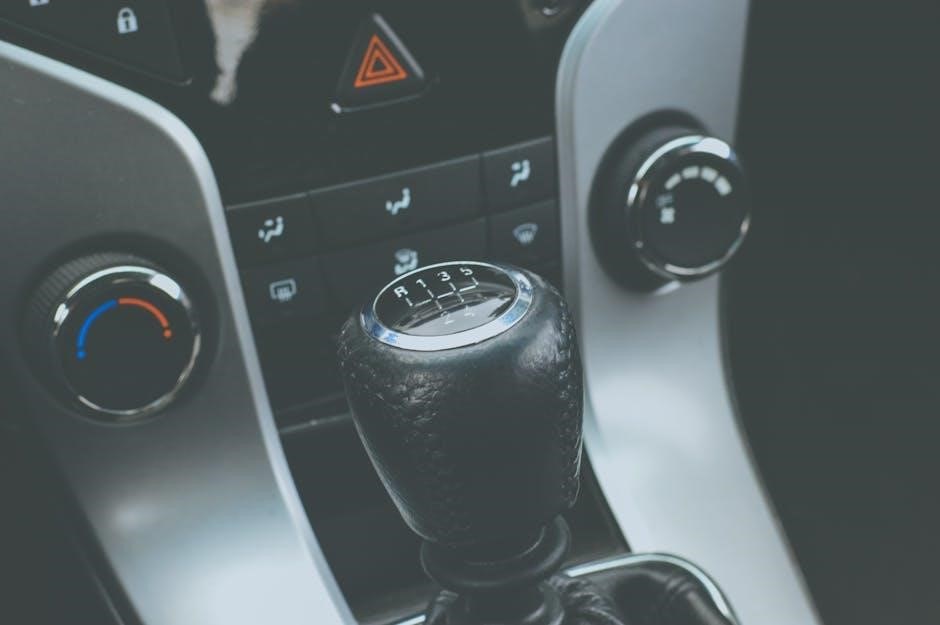
The primary distinction in 3-speed manual shifters lies in their placement⁚ floor-mounted or column-mounted. Floor shifters‚ the focus of this guide‚ offer a more direct and often sportier driving experience. They’re typically preferred by enthusiasts for their enhanced feel and control during gear changes. The shifter lever is positioned within easy reach on the floor of the vehicle‚ promoting a more engaging connection with the transmission. Column shifters‚ conversely‚ are mounted on the steering column. While convenient in older vehicles‚ they generally offer less precise shifting and a less direct feel compared to floor-mounted options. The column-mounted design was prevalent in earlier vehicles‚ particularly those with three-speed manual transmissions‚ like some 1939 Plymouth models. The shift linkage and mechanism differ significantly between the two types‚ making conversion from a column shifter to a floor shifter a more involved process‚ often requiring specialized installation kits and potentially modifications to the vehicle’s interior. The choice depends largely on personal preference‚ vehicle design‚ and the desired driving experience.

Installation Kits and Components

Successful 3-speed manual transmission floor shifter installation hinges on acquiring the correct kit and understanding its components. Comprehensive kits‚ such as those offered by Mastershift‚ typically bundle all necessary linkage‚ mounting hardware‚ and a shifter boot. This ensures a smoother installation process. The included linkage is often heat-treated for enhanced durability and longevity‚ a critical factor for a component subjected to repetitive stress. Beyond the complete kits‚ individual components might need sourcing depending on the specific application and vehicle. These could include specialized adapters for compatibility with various transmission types‚ different mounting brackets to accommodate unique chassis configurations‚ and replacement bushings for worn or damaged components in the existing linkage. Careful examination of the kit’s contents alongside the vehicle’s existing setup is crucial before starting the installation. Remember to check for compatibility with your specific transmission and vehicle model to avoid unnecessary complications or the need for further modifications during the installation process. The quality of the components significantly impacts the overall performance and longevity of the new shifter.

Popular Brands and Models

Several reputable brands dominate the 3-speed manual transmission floor shifter market‚ each offering distinct features and quality levels. Hurst Performance is a prominent name‚ renowned for its high-performance shifters and comprehensive installation kits. Their Mastershift series‚ for example‚ is popular for its precise gear selection and compatibility with various vehicles. Gennie Shifters provides a compelling alternative‚ emphasizing robust construction using hand-polished stainless steel for both durability and aesthetic appeal. Their shifters are designed for compatibility with numerous Tremec transmissions and popular muscle car models like Mustangs and Camaros. JEGS High Performance also offers a range of universal 3-speed manual floor shifters‚ catering to a broader spectrum of applications. When selecting a brand and model‚ consider factors such as the specific transmission type in your vehicle‚ desired shift feel (e.g.‚ effortless versus performance-oriented)‚ and budget constraints. Reading online reviews and comparing specifications from different manufacturers can help narrow down the options and ensure you choose a shifter that meets your individual needs and preferences. Remember to verify compatibility with your vehicle’s make‚ model‚ and year before making a purchase.

Compatibility and Applications

The compatibility of a 3-speed manual transmission floor shifter hinges on several key factors‚ primarily the type of transmission already installed in your vehicle. Many shifters are designed to work with specific transmission makes and models‚ such as Tremec units frequently found in classic muscle cars. Before purchasing‚ meticulously check the manufacturer’s specifications to ensure compatibility with your particular transmission. Furthermore‚ the year and model of your vehicle play a crucial role. Older vehicles might necessitate different mounting hardware or linkage adjustments compared to newer models. Some universal shifters exist‚ but even these may require modifications or custom fabrication for proper fitment in certain applications. Beyond the transmission itself‚ consider the vehicle’s chassis and interior layout. Sufficient clearance must exist around the shifter for comfortable operation and to avoid interference with other components. Applications range widely‚ from classic American muscle cars to vintage trucks and even some custom-built vehicles. However‚ direct bolt-in compatibility is not guaranteed across the board‚ and some level of mechanical aptitude or professional installation may be required. Always consult detailed compatibility charts and installation guides provided by the manufacturer to avoid potential complications and ensure a successful installation.

Installation Process⁚ A Step-by-Step Guide

Installing a 3-speed manual transmission floor shifter typically involves several key steps. Begin by disconnecting the battery’s negative terminal to prevent electrical shorts. Next‚ carefully remove the existing shifter and linkage components. This often requires removing the shift knob‚ boot‚ and any connecting rods or cables. Consult your vehicle’s service manual or the shifter’s installation instructions for precise details. Once the old components are removed‚ thoroughly clean the area to ensure a secure installation of the new shifter. Position the new shifter according to the manufacturer’s instructions and securely attach it to the transmission. Connect the linkage components‚ ensuring proper alignment and free movement. If using a kit‚ follow the included instructions carefully‚ as these kits often provide specialized components and procedures. After installation‚ carefully reassemble any interior trim pieces. Always double-check all connections and linkages for proper function before reconnecting the battery. Test the shifter thoroughly to ensure smooth‚ accurate gear changes in all positions. If any issues arise during installation or operation‚ refer to the troubleshooting section of this guide or consult a qualified mechanic. Remember‚ safety is paramount; if unsure about any step‚ seek professional assistance.

Troubleshooting Common Issues

Several common problems can arise with 3-speed manual transmission floor shifters. One frequent issue is difficulty shifting gears‚ often caused by worn linkage components or improper adjustment. Inspect the linkage for bent or damaged parts‚ and ensure all connections are secure and properly lubricated. Adjusting linkage rods may resolve this. Another issue is imprecise shifting‚ where gears don’t engage smoothly or the shifter feels loose. This could indicate worn bushings or a misaligned shifter. Replacing worn bushings or realigning the shifter can remedy this. If the shifter feels stiff or binds‚ the problem might be related to binding linkage components or insufficient lubrication. Check for obstructions or interference‚ and lubricate all moving parts. If a gear refuses to engage‚ carefully inspect the linkage for any obstructions or misalignments and ensure the clutch is fully disengaged. A grinding noise during shifting usually points to a clutch issue or worn transmission components. The clutch itself may need replacement or adjustment. Always consult your vehicle’s service manual or the shifter manufacturer’s instructions for specific troubleshooting steps and adjustments. If problems persist after trying these solutions‚ it’s best to consult a qualified mechanic to diagnose and repair any complex transmission problems.

Maintenance and Upkeep

Regular maintenance is crucial for ensuring the longevity and smooth operation of your 3-speed manual transmission floor shifter. Begin by periodically inspecting the linkage for wear and tear. Look for any signs of bending‚ cracks‚ or excessive play in the joints. Replace damaged components promptly to prevent further issues. Lubrication is another key aspect of maintenance. Apply a high-quality lubricant‚ such as silicone-based grease‚ to all moving parts of the linkage‚ including bushings and pivot points. This will reduce friction and ensure smooth shifting. The frequency of lubrication depends on usage and environmental conditions‚ but a yearly inspection and lubrication are generally recommended. Pay close attention to the shift knob as well. Over time‚ the threads can wear‚ leading to looseness or slippage. Tighten the shift knob periodically‚ and if necessary‚ replace it with a new one. Regularly check the boot surrounding the shifter for any tears or damage. A damaged boot can allow dust and debris to enter the mechanism‚ causing premature wear. Replace the boot if it shows any signs of wear. Finally‚ be mindful of the overall condition of the transmission. A problematic transmission will negatively impact the shifter’s performance. Regular transmission service and fluid changes are vital for maintaining optimal performance.

Shift Knob Selection and Compatibility

Selecting the right shift knob is crucial for both aesthetics and functionality. The most common thread size for shift knobs is 3/8-16 inch‚ but variations exist‚ such as 3/8-24 inch. Always verify your shifter’s thread pitch before purchasing a knob to ensure compatibility. Consider the material of the shift knob. Popular options include metal (aluminum‚ stainless steel)‚ resin‚ wood‚ and leather. Metal knobs offer durability and a sporty feel‚ while wood and leather provide a more classic or luxurious touch. Resin knobs are often lighter and more affordable. The weight and size of the knob also influence the driving experience. Heavier knobs offer a more substantial feel‚ while lighter knobs allow for quicker shifts. Consider your personal preference and driving style when making your choice. The knob’s design is another important factor. Various shapes‚ sizes‚ and styles are available‚ allowing you to personalize your shifter. Some knobs feature added features‚ such as built-in illumination or ergonomic grips. Before installing‚ ensure the knob’s dimensions are compatible with your shifter and hand size. A poorly fitting knob can hinder shifting and create discomfort. Remember to check for any additional adapters or mounting hardware required for installation. Choose a knob that complements the overall style and feel of your vehicle’s interior.

Manuals

sc9120b manual

First Alert SC9120B⁚ A Comprehensive Guide

This guide provides a complete overview of the First Alert SC9120B hardwired combination smoke and carbon monoxide alarm. Learn about installation, testing, maintenance, troubleshooting, alarm signals, battery backup, interconnectivity, safety, regulatory compliance, end-of-life indicators, and optimal placement for maximum protection in your home.

The First Alert SC9120B is a combination smoke and carbon monoxide alarm designed for hardwired installation in residential and institutional settings, including bedrooms. This dual-purpose alarm provides crucial protection against two leading household threats⁚ fire and carbon monoxide poisoning. A key feature is its 9-volt battery backup, ensuring continued operation during power outages. The SC9120B utilizes advanced sensing technologies to detect both fast-flaming and slow-smoldering fires, offering reliable protection against various fire types. Its electrochemical carbon monoxide sensor accurately detects potentially lethal CO levels. The unit features a single button for testing, silencing, and resetting the alarm, simplifying operation. Additionally, the SC9120B includes latching features for both alarm and low-battery conditions, providing clear indication of past events. The alarm’s loud 85-decibel warning signal is designed to effectively alert occupants even during sleep. Finally, the SC9120B boasts an end-of-life signal, prompting timely replacement to maintain optimal safety levels.

Installation Guide⁚ Wiring and Placement

Before commencing installation, ensure the power to the circuit is switched off. Carefully follow the wiring instructions provided in the separate installation guide included with the First Alert SC9120B. Connect the alarm to the existing wiring according to the color-coded diagrams. Securely mount the base to the wall or ceiling using the provided screws, ensuring a stable and level installation. Optimal placement is crucial for effective detection. For smoke alarms, install one on each level of your home, inside every bedroom, and in hallways near sleeping areas, at least 4-12 inches from the wall/ceiling intersection. For carbon monoxide alarms, place one outside each separate sleeping area. Avoid locations near cooking appliances, sources of combustion (furnaces, water heaters), extremely humid areas, or areas with turbulent air currents. Maintain a minimum distance of 6 meters from combustion sources if possible; otherwise, place as far away as feasible. Do not install in garages, kitchens, furnace rooms, crawl spaces, unfinished attics, or extremely dusty, dirty, or greasy areas. Always refer to the complete installation guide for detailed instructions and safety precautions before beginning the installation process.

Testing and Maintenance Procedures

Regular testing is essential to ensure the First Alert SC9120B functions correctly. Perform a weekly test using the built-in test button. This will activate the alarm, confirming its operational status. The alarm should sound loudly, indicating proper functionality. If the alarm fails to sound, immediately investigate the issue, checking battery connections and power supply. Monthly, inspect the alarm for any signs of damage or dust accumulation. Gently clean the unit using a soft brush or cloth to remove any debris that may interfere with sensor performance. Replace the 9-volt backup battery every six months, regardless of whether the alarm has been activated. Always use a fresh, high-quality 9-volt battery for optimal performance and longevity. The SC9120B has an end-of-life indicator that will signal when the unit needs replacement after approximately 10 years. This indicator will provide both audible and visual warnings, prompting you to replace the entire unit promptly. Do not attempt to repair the alarm yourself; replace it with a new compatible model. Regular maintenance and testing significantly enhance the life and effectiveness of your SC9120B, providing crucial early warnings in emergency situations.

Troubleshooting Common Issues

If the First Alert SC9120B alarm continuously chirps, this usually indicates a low battery condition. Replace the 9-volt backup battery immediately. If the chirp persists after battery replacement, the alarm itself might require replacement. A malfunctioning alarm may fail to activate during a test. If the alarm doesn’t sound during a weekly test, check the power supply and battery connections, ensuring they are secure and correctly installed. If the problem persists, replace the entire unit. False alarms can be triggered by dust, insects, or excessive humidity. Regular cleaning and proper placement, avoiding areas with high humidity or dust, can minimize this issue. If the alarm sounds intermittently, consider relocating the unit away from potential sources of interference, such as cooking appliances or other heat sources. Remember that the SC9120B is designed to detect both smoke and carbon monoxide; differentiating between the two alarm signals is important for appropriate responses. If you’re unsure about the cause of an alarm activation, consult the user manual or contact First Alert customer support for assistance. Always prioritize safety and replace a malfunctioning alarm promptly to ensure continued protection.

Understanding Alarm Signals⁚ Smoke vs. Carbon Monoxide

The First Alert SC9120B utilizes distinct alarm signals to differentiate between smoke and carbon monoxide (CO) threats. A pulsing red LED light and a loud, continuous alarm sound indicate a smoke detection event. This alerts you to a potential fire hazard, requiring immediate evacuation and emergency services notification. In contrast, a steady red LED light accompanied by a pulsating alarm sound signals the detection of carbon monoxide. This signifies the presence of a potentially deadly, odorless gas, necessitating immediate action to ventilate the area and seek fresh air. The SC9120B’s combination functionality offers enhanced safety, promptly warning you of either smoke or CO threats. Understanding the difference between these alarm patterns is crucial for appropriate response. In the event of a smoke alarm, prioritize evacuation, while a CO alarm requires immediate ventilation and potential medical attention. Familiarize yourself with the alarm signals to ensure effective response in any emergency situation. Regular testing helps ensure the alarm functions correctly, providing timely alerts in critical situations.

Battery Backup and Replacement

The First Alert SC9120B incorporates a 9-volt battery backup, ensuring continued operation even during power outages. This crucial safety feature provides uninterrupted protection, alerting you to potential fire or carbon monoxide hazards regardless of electrical supply. The battery serves as a reliable secondary power source, maintaining the alarm’s functionality in the event of a power failure. Regular battery checks are essential to guarantee its effectiveness. It’s recommended to inspect the battery at least every six months, replacing it if necessary. A low-battery warning signal will typically sound to alert you when the battery requires replacement. Promptly replacing the battery is vital to sustain the alarm’s protective capabilities. Failure to do so may compromise its ability to detect and signal dangerous conditions. When replacing the battery, ensure you use a fresh 9-volt alkaline battery of the recommended type. Incorrect battery installation or the use of a depleted battery could render the alarm inoperable. Always refer to the manufacturer’s instructions for correct battery placement and disposal procedures. Maintaining a functional battery backup is critical for ensuring the continued safety and protection offered by your SC9120B alarm.

Interconnectivity with Other First Alert Devices

The First Alert SC9120B offers smart interconnect capabilities, allowing it to communicate with other compatible First Alert smoke and carbon monoxide alarms. This interconnected system enhances home safety by creating a network of interconnected detectors. When one alarm in the network detects a threat, such as smoke or carbon monoxide, all interconnected units will sound simultaneously. This feature ensures that everyone in the house is alerted regardless of their location, providing a unified and comprehensive warning system. The interconnected system uses a single wire to transmit both smoke and carbon monoxide signals between the units, simplifying installation and minimizing wiring complexity. To utilize the interconnect feature, ensure all alarms are compatible and correctly wired according to the manufacturer’s instructions. Proper installation is critical to ensure the reliability and effectiveness of the interconnected network. Consult the First Alert manual for specific guidance on wiring and compatibility requirements. By establishing an interconnected network, the SC9120B maximizes the effectiveness of your home’s safety system, providing a faster and more widespread alert in the event of a fire or carbon monoxide leak. This enhanced response time can be crucial in emergency situations.

Safety Precautions and Recommendations

Prioritize safety when installing and using the First Alert SC9120B. Always turn off the power supply before installing or removing the alarm to prevent electrical shock. Never paint over the unit; paint can obstruct the sensors, hindering proper operation. Keep the alarm clean and free from dust, dirt, or grease to maintain optimal sensitivity. Regular testing is crucial; test the alarm weekly to ensure it functions correctly. Immediately replace the alarm if it malfunctions or fails to respond during testing. The alarm’s loud sound can be harmful to hearing at close range; maintain a safe distance when the alarm is sounding. Proper placement is vital. Avoid installing the SC9120B in areas prone to high humidity, extreme temperatures, or turbulent air currents, as these conditions can affect its performance. Follow all instructions in the manual for optimal installation and maintenance. Remember that smoke and carbon monoxide alarms are designed to provide early warning, but they are not a substitute for fire safety practices. Maintain a smoke-free environment, properly store flammable materials, and regularly check electrical appliances for safety. Ensure you have working fire extinguishers and a well-rehearsed escape plan for your household.

Regulatory Compliance and Standards

The First Alert SC9120B adheres to stringent safety and performance standards. It’s designed and manufactured to meet or exceed the requirements of various regulatory bodies, ensuring reliable operation and user safety. Specific compliance certifications vary depending on the region of sale, but generally include adherence to ULC S531 and NFPA 72 standards for smoke alarms. These standards dictate testing procedures and performance criteria to guarantee the alarm’s ability to detect smoke effectively and reliably alert occupants in case of a fire. The alarm also complies with relevant carbon monoxide (CO) detection standards, ensuring accurate and timely detection of dangerous CO levels. These standards often include specifications for sensor technology, response times, alarm levels, and other critical performance parameters. Before installation, it’s crucial to check your local building codes and regulations to ensure that the placement and installation of the SC9120B comply with all applicable laws and guidelines. This will help ensure the alarm operates effectively and legally within your area. Consult your local fire department or building authority for additional guidance if needed. Always refer to the most up-to-date documentation for the most current regulatory information.

End-of-Life Indicators and Replacement

The First Alert SC9120B incorporates a crucial end-of-life (EOL) indicator system to signal when the unit needs replacement. This is critical for maintaining optimal fire and carbon monoxide protection within your home. After a specified period (typically ten years from the manufacturing date), the alarm will activate its EOL signal. This signal typically consists of a series of audible chirps and/or a flashing visual indicator light, providing a clear and unmistakable warning that the alarm’s internal components may no longer function reliably. Ignoring this signal compromises the safety of your household. The alarm’s sensors and internal electronics degrade over time, potentially impacting their sensitivity and accuracy in detecting smoke or carbon monoxide. A malfunctioning alarm could fail to alert you to a dangerous situation, resulting in potentially serious consequences. Therefore, replacing the unit promptly upon receiving the EOL signal is paramount. Do not attempt to repair or service the alarm yourself; replacing it with a new, certified unit is the only way to ensure ongoing protection against fire and carbon monoxide hazards. Always purchase replacement alarms from reputable retailers to guarantee compliance with safety standards. Remember to check the manufacturing date on your existing alarm to determine its remaining lifespan.

Where Not to Install the SC9120B

Careful placement of the SC9120B is crucial for its effectiveness. Avoid locations where environmental factors could hinder its operation or trigger false alarms. Do not install the unit in garages, kitchens, furnace rooms, crawl spaces, or unfinished attics due to the presence of combustion particles and fluctuating temperatures. These areas often experience high levels of dust, grease, or humidity, which can clog the sensors and lead to malfunctions or inaccurate readings. Similarly, avoid extremely dusty, dirty, or greasy environments. Keep the alarm at least 6 meters (20 feet) away from fuel-burning appliances such as stoves, furnaces, water heaters, and space heaters whenever possible. In smaller homes where this distance isn’t feasible, maximize the distance to reduce the risk of false alarms caused by proximity to combustion sources. Avoid installing the alarm within 1.5 meters (5 feet) of cooking appliances or in areas with turbulent airflow, such as near ceiling fans or open windows, as air currents can prevent smoke or carbon monoxide from reaching the sensors reliably. High humidity areas, such as bathrooms, laundry rooms, or near humidifiers, can also affect performance and should be avoided. Likewise, steer clear of insect-infested areas, as insects can obstruct the sensor openings. Remember, correct placement ensures the SC9120B operates efficiently and reliably, providing accurate and timely alerts.

Manuals

diono radian 3rxt manual

Diono Radian 3RXT Manual⁚ A Comprehensive Guide

This guide provides a complete overview of the Diono Radian 3RXT manual, covering installation in rear-facing and forward-facing modes, harness usage, booster mode instructions, weight and height limits, safety features, tether strap use, vehicle compatibility, and troubleshooting common issues. Information on locating the manual for both newer and older models is also included, along with contact details for Diono customer service.

Finding the Diono Radian 3RXT Manual

Locating your Diono Radian 3RXT manual is crucial for ensuring the safe and proper use of your car seat. For car seats manufactured before January 2020, the manual is conveniently stored within a pocket sewn into the seat cover. Look for a small icon depicting a manual; this indicates the location of the storage pocket. Inside, you’ll find the comprehensive instruction booklet. For newer models, the process might differ. Check the Diono website’s product support section; they often provide downloadable PDF versions of their manuals. Alternatively, contacting Diono customer service directly is another reliable method. They can assist you in obtaining a digital copy or guide you to a physical manual if necessary. Remember, having access to the instruction manual is paramount for understanding the safety features, installation procedures, and proper usage of your Diono Radian 3RXT car seat. This ensures your child’s safety and peace of mind.

Locating the Manual⁚ Older Models vs. Newer Models

The method for finding your Diono Radian 3RXT manual differs depending on the manufacturing date of your car seat. For older models (manufactured before January 2020), a sewn-in pocket within the seat cover houses the printed manual. Look for a small icon marking the pocket’s location. This pocket is specifically designed for storing the instruction booklet and is a key feature of older models. Newer Diono Radian 3RXT car seats may not utilize this integrated storage method. Instead, you’ll likely need to consult the Diono website’s product support section. Here you should find downloadable PDF versions of the manual for your specific car seat model. This online approach allows for easy access and ensures you have the latest instructions. If you encounter difficulties locating your manual online or in the car seat itself, contacting Diono’s customer service department is recommended. They can provide assistance in locating the appropriate manual for your car seat’s model and manufacturing date.

Understanding the Radian 3RXT SafePlus Series

The Diono Radian 3RXT SafePlus series represents a line of all-in-one convertible car seats renowned for their extended rear-facing and forward-facing capabilities. This series includes models such as the Radian 3R SafePlus, Radian 3RXT SafePlus, and the Radian 3RXT SafePlus Max. A key feature of these models is their adaptability, growing with your child from infancy through to booster seat usage. The SafePlus designation highlights enhanced safety features beyond the standard Radian 3RXT, often incorporating improvements in harness design, padding, and overall structural integrity. These seats are engineered with a steel core, providing superior strength and protection in the event of a collision. Understanding the specific features and functionalities of your particular SafePlus model—whether it’s the standard Radian 3RXT SafePlus or the Max variant—is crucial for correct installation and use. Always refer to the specific instructions provided in your model’s user manual for detailed guidelines on installation, harness adjustment, and other safety-related aspects. The comprehensive manual ensures you utilize the seat’s full safety potential.
Installation Guide⁚ Rear-Facing Mode

Installing your Diono Radian 3RXT rear-facing is crucial for optimal safety. Begin by ensuring your vehicle’s seat is properly reclined, consulting your vehicle’s owner’s manual for specifics. Secure the car seat using either the vehicle’s seat belt or LATCH system, following the instructions provided in your Radian 3RXT manual meticulously. Pay close attention to the correct tightening procedures; a snug fit is paramount. After securing the base, carefully place your child in the seat, ensuring the harness straps are properly adjusted and snug against their bodies. The harness should sit at or below the child’s shoulders. Check for any slack in the straps; they shouldn’t be loose. The crotch buckle should be properly fastened, and the chest clip should be positioned at armpit level. Double-check that the car seat is securely installed and doesn’t move more than one inch side-to-side or front-to-back at the base. If using LATCH, ensure the lower anchors are correctly engaged and the tether strap (if applicable) is secured to the designated vehicle anchor point. Regularly inspect the installation to guarantee it remains secure and properly adjusted as your child grows. Remember, consistent, correct installation is critical for effective protection.

Installation Guide⁚ Forward-Facing Mode

Transitioning your Diono Radian 3RXT to forward-facing requires careful attention to detail. Before beginning, ensure your child meets the minimum height and weight requirements specified in the manual. Once ready, adjust the car seat’s recline to the appropriate setting for forward-facing, referring to the instructions in your manual. Secure the car seat using either the vehicle’s seat belt or LATCH system, following the provided instructions precisely. Proper tightening is crucial; the car seat shouldn’t shift more than one inch in any direction. After securing the base, carefully place your child in the seat and adjust the harness straps to fit snugly. The harness should sit at or slightly above the child’s shoulders. Ensure there’s no slack in the straps; they should be comfortably tight against your child’s body. Fasten the crotch buckle and position the chest clip at armpit level. Crucially, utilize the top tether strap if your vehicle is equipped with a tether anchor point; this significantly improves stability and reduces forward movement in a collision. Refer to your vehicle’s owner’s manual for tether anchor point location. Finally, always double-check the installation to ensure it’s secure and correctly adjusted. Remember, proper installation is fundamental to the car seat’s protective capabilities.

Harness System and Usage

The Diono Radian 3RXT utilizes a five-point harness system designed for optimal safety. Understanding its proper use is paramount. Always ensure the harness straps are snug against your child’s body, with no slack. The harness should sit at or slightly above your child’s shoulders, and the chest clip should be positioned at armpit level. Adjust the straps as your child grows, maintaining a snug fit at all times. Never route the harness straps over bulky clothing, as this compromises its effectiveness. The crotch buckle should be securely fastened, keeping your child safely secured within the car seat. Regularly inspect the harness for any signs of wear or tear. Damaged straps must be replaced immediately. The harness system is designed to distribute impact forces across multiple points, minimizing injury to your child during a collision. When using the car seat in booster mode, the harness is removed, and the vehicle’s seat belt is used for restraint, always following the manufacturer’s instructions and ensuring a proper and secure fit. Remember, a properly adjusted and maintained harness system is vital for your child’s safety, so always double-check before each trip. In case of any damage or uncertainty, contact Diono customer service for assistance.

Booster Mode Instructions

Once your child outgrows the harness stage, the Diono Radian 3RXT transitions seamlessly into booster mode. This involves removing the harness and utilizing the vehicle’s seat belt to secure your child. Before transitioning, ensure your child meets the minimum height and weight requirements specified in the manual. Proper booster mode installation is crucial for safety. The vehicle’s lap and shoulder belt must fit snugly across your child’s hips and shoulders, respectively, with no slack. The lap belt should lie low across the thighs, and the shoulder belt should sit across the collarbone, not the neck or face. The Radian 3RXT’s design incorporates features to optimize booster mode functionality. These may include belt guides or positioning aids to help secure the vehicle’s seat belt correctly. Always refer to the manual for specific instructions regarding your car seat model and its features. Regularly check the fit and adjust as needed as your child grows. Ensure that the vehicle’s seat belt fits snugly and doesn’t allow for excessive movement or looseness. Never compromise on safety. If you encounter any difficulties during the transition or if you are unsure about the proper fit, consult the Diono Radian 3RXT manual or contact Diono customer service for assistance to guarantee your child’s safety.

Weight and Height Limits

Understanding the weight and height limits of your Diono Radian 3RXT is paramount for your child’s safety. These limits vary depending on the car seat’s mode of use (rear-facing, forward-facing, or booster). The manual clearly outlines these restrictions for each stage. Exceeding these limits compromises the car seat’s ability to provide adequate protection in a crash. Always check the manufacturer’s specifications before installing the car seat. Regularly monitor your child’s growth and refer to the manual to ensure they remain within the appropriate weight and height ranges for the selected mode. Failure to do so could result in improper restraint and increased risk of injury. The weight limits are generally expressed in pounds or kilograms, while height limits are typically given in inches or centimeters. Pay close attention to both measurements, as one may be exceeded before the other. If your child approaches either limit, it’s time to transition to the next stage of car seat usage or consider a different car seat entirely, depending on your child’s size and age. Prioritize safety and consult the manual frequently to maintain optimal protection for your child. Remember that exceeding weight or height limits can significantly impact the effectiveness of the car seat’s safety features.

Safety Features and Their Importance

The Diono Radian 3RXT boasts several crucial safety features designed to protect your child in the event of a collision. Understanding these features and their proper usage is critical. The steel-reinforced frame provides exceptional structural integrity, absorbing impact forces and minimizing the transfer to your child; The 5-point harness system securely restrains your child, preventing ejection or excessive movement during a crash. Proper harness adjustment is vital; refer to the manual for detailed instructions. The energy-absorbing headrest and side impact protection help reduce head and neck injuries in side collisions, common accident types. The integrated LATCH system (Lower Anchors and Tethers for Children) allows for secure installation in many vehicles, while the tether strap further enhances stability during forward-facing use. Always utilize the tether when available; it significantly reduces the risk of rotation and forward movement during a crash; Regularly inspect the car seat for any signs of wear and tear, paying particular attention to the harness, buckles, and frame. Replace the car seat if it shows any signs of damage from a collision or significant wear. Understanding and correctly using these safety features is paramount in ensuring your child’s safety and maximizing the protective capabilities of the Diono Radian 3RXT.

Proper Use of Tether Straps

The tether strap is a critical safety feature of the Diono Radian 3RXT, significantly enhancing your child’s protection, especially in forward-facing mode; It’s designed to limit the car seat’s forward movement during a sudden stop or collision, reducing the risk of head and neck injuries. Proper tether usage requires careful attention to detail. First, locate the tether anchor point in your vehicle; this is usually situated on the rear deck, behind the rear seat. Next, locate the tether strap on the car seat; it’s typically positioned at the top center of the seatback. Thread the tether strap through the vehicle’s tether anchor, ensuring it’s securely fastened. Avoid twisting the strap or leaving excess slack. A correctly installed tether strap should be taut but not excessively tight. Over-tightening could damage the car seat or the vehicle’s interior. Always refer to both your vehicle’s owner’s manual and the Diono Radian 3RXT manual for specific instructions regarding tether anchor locations and proper attachment methods. Never use the tether strap in rear-facing mode; it’s solely intended for forward-facing use. Regularly check the tether strap for any signs of damage or wear and replace it if necessary. A properly used tether strap is a crucial component of your child’s safety, offering additional protection beyond the vehicle’s seatbelt.

Vehicle Compatibility and Airbag Considerations

Before installing the Diono Radian 3RXT, carefully review your vehicle’s owner’s manual for specific instructions regarding child restraint installation. Not all vehicles are equally compatible with all car seats, and certain seating positions might be unsuitable due to seatbelt configuration or structural limitations. Pay close attention to the vehicle’s seatbelt system; it must properly engage with the car seat’s lower anchors and belt path to ensure a secure fit. The Diono Radian 3RXT manual provides detailed information on compatible seatbelt systems, but always verify compatibility with your specific vehicle model; Airbag deployment poses a significant safety concern when using a child car seat. Consult your vehicle’s owner’s manual to determine the safest seating position for your child, considering the type of airbags present (front, side, curtain). In vehicles with front passenger airbags, installing the Diono Radian 3RXT in the front passenger seat might be unsafe, especially for infants and toddlers. It is generally recommended to position the car seat in the rear of the vehicle, ideally in the center, as far away from any airbags as possible. Remember, the safest installation is one that adheres to both the vehicle and car seat manufacturer’s guidelines. If unsure about proper installation, seek guidance from a certified child passenger safety technician.

Troubleshooting Common Issues

The Diono Radian 3RXT, while robust, may present occasional challenges. If the car seat’s harness is difficult to adjust, ensure it’s correctly threaded through all the appropriate slots and hasn’t become tangled; Refer to the manual’s harness adjustment section for illustrated guidance. A loose or improperly installed car seat is a serious safety hazard. Double-check all connections to the vehicle’s seatbelt or LATCH system; a securely fastened car seat will not move significantly when tugged. If the car seat feels unstable or wobbles, re-examine your installation procedure. The manual contains detailed illustrations and instructions to assist with correct installation. If the car seat’s recline angle is incorrect, verify that the recline adjustments are properly engaged and that the car seat’s base is level. Difficulty securing the car seat’s tether strap might indicate the tether anchor in your vehicle is inaccessible or improperly positioned. Consult your vehicle’s owner’s manual for its location and ensure the strap is taut and not twisted. Persistent issues may require professional assistance. Contact Diono customer service or a certified child passenger safety technician for guidance. Remember, a correctly installed and functioning car seat is paramount to your child’s safety. Do not hesitate to seek expert help if needed.

Contacting Diono Customer Service

Should you encounter difficulties understanding the Diono Radian 3RXT manual, require assistance with installation, or experience any problems with your car seat, Diono offers comprehensive customer support. Their website, typically found at diono.com, provides a wealth of resources, including FAQs, instructional videos, and contact information. You can usually find a dedicated customer service phone number or email address readily accessible on their website’s support or contact page; Before contacting them, it’s helpful to gather relevant information, such as your car seat’s model number and serial number (often found on a label attached to the seat itself), as well as a clear description of the issue you’re facing. Detailed descriptions, including photographs if possible, will enable Diono’s customer service representatives to quickly understand your situation and provide appropriate assistance. Be prepared for potential wait times, particularly during peak periods. Consider checking their website for FAQs or online chat options, which may offer immediate solutions to common problems. Remember that Diono prioritizes the safety of your child, so don’t hesitate to reach out if you have any concerns about the correct installation or use of your Radian 3RXT car seat.