
manual transfer switch 50 amp
Understanding 50 Amp Manual Transfer Switches
Manual transfer switches offer a safe way to connect a generator during outages. A 50 amp model provides substantial power for essential household circuits, ensuring reliable backup electricity.
These switches allow you to isolate your home from the grid while powering selected circuits, preventing dangerous backfeeding to utility lines.
What is a Manual Transfer Switch?
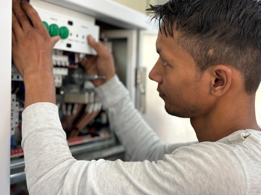
A manual transfer switch is a crucial safety device enabling the connection of a generator to a home’s electrical system during power outages. Unlike automatic systems, it requires manual operation – you physically switch the power source.
Specifically, a 50 amp manual transfer switch manages a higher electrical load, supporting more appliances and circuits than lower amperage models. It isolates your home from the utility grid, preventing dangerous backfeeding – electricity flowing back into power lines – while allowing generator power distribution.
Installation involves wiring the switch to both the main electrical panel and a generator inlet, typically utilizing a double-pole breaker for safe operation.
Why Choose a 50 Amp Transfer Switch?
Opting for a 50 amp manual transfer switch provides significant advantages for homeowners needing robust backup power. This amperage allows connection to a generator capable of running essential appliances – refrigerators, furnaces, well pumps, and lighting – simultaneously, offering greater comfort during outages.
Compared to smaller wattage switches, a 50 amp model offers flexibility in circuit selection. It’s ideal for homes with higher power demands or those wanting to power more critical loads. Furthermore, it’s a cost-effective solution, balancing capability with affordability compared to automatic transfer systems.
Proper wiring and breaker installation are vital for safe and efficient operation.

Safety First: Important Considerations
Electrical work is dangerous! Always prioritize safety when installing a 50 amp transfer switch, adhering to all local codes and taking necessary precautions to avoid hazards.
Local Electrical Codes and Permits
Before installing any 50 amp manual transfer switch, thoroughly research and understand your local electrical codes. These regulations vary significantly by location and are crucial for a safe and compliant installation.
Many jurisdictions require permits for electrical work, including transfer switch installations. Obtaining the necessary permits ensures your work is inspected and meets safety standards. Failure to comply can result in fines or require costly rework.
Contact your local building department or a qualified electrician to determine specific requirements in your area. They can provide guidance on acceptable wiring methods, grounding techniques, and required inspections. Prioritizing code compliance safeguards your home and family.
Working with Electricity: Risks and Precautions
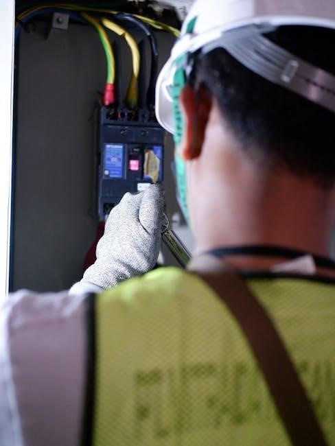
Installing a 50 amp manual transfer switch involves working with potentially lethal electricity. Extreme caution is paramount. Always disconnect the main power supply to your home before beginning any electrical work. Verify the power is off using a non-contact voltage tester.
Never work alone; have someone nearby in case of emergency. Wear appropriate personal protective equipment (PPE), including insulated gloves and safety glasses. If you are uncomfortable or lack experience with electrical wiring, hire a qualified, licensed electrician.
Incorrect wiring can cause fires, electrical shock, or damage to your appliances. Double-check all connections and follow the manufacturer’s instructions meticulously. Remember, safety is non-negotiable when dealing with electricity.

Components of a 50 Amp Manual Transfer Switch System
A complete system includes the transfer switch, a compatible generator, appropriately sized wiring and connectors, and a double-pole breaker for safe operation.
The Transfer Switch Itself
The 50 amp manual transfer switch is the central component, designed to safely route power. It features distinct input and output terminals, allowing disconnection from the utility grid and connection to a generator.
These switches typically have pre-drilled mounting holes for easy installation next to your main electrical panel. They are constructed with durable materials to withstand electrical loads and ensure long-term reliability.
Champion models, for example, utilize armored cable for secure connections. The switch’s configuration allows for selective circuit powering, avoiding overloading the generator. Proper selection ensures compatibility with your generator’s output.
Generator Requirements (50 Amp Compatibility)
A 50 amp transfer switch demands a generator capable of delivering sufficient wattage. Typically, a generator producing at least 7,500 to 10,000 watts is recommended to handle the load, accounting for starting surges of appliances.
Ensure the generator’s outlet configuration matches the transfer switch’s inlet – often a 14-50 receptacle. The generator must also have the appropriate voltage (usually 120/240V) for compatibility.
Backfeeding through a 50 amp breaker requires careful consideration of generator capacity. Always verify the generator’s continuous and peak wattage ratings before connecting it to the transfer switch.
Necessary Wiring and Connectors
For a 50 amp transfer switch, you’ll need appropriately sized wiring – typically 6 AWG copper or 4 AWG aluminum SEU cable – to handle the current. This cable connects the main panel to the switch and the switch to the generator inlet.
Use weatherproof connectors and conduit for exterior runs. Quality wire nuts are essential for secure connections within the panels. A 14-50 receptacle and plug are standard for generator connection.
Ensure all wiring meets local electrical codes and is rated for the intended application, prioritizing safety and preventing overheating.
Appropriate Breakers
A 50 amp manual transfer switch requires a double-pole 50 amp breaker in your main electrical panel. This breaker isolates your home circuits from the utility grid when the generator is running, preventing backfeeding.
The generator itself may also require a breaker, often integrated into the generator’s power cord or a separate breaker box. Ensure the generator breaker’s rating doesn’t exceed the transfer switch’s capacity.
Correct breaker sizing is crucial for safety and preventing damage to the electrical system. Always consult local codes and a qualified electrician.
Installation Process: Step-by-Step Guide
Installing a 50 amp transfer switch involves safely disconnecting power, mounting the switch, carefully wiring it to both the main panel and generator inlet, and installing breakers.
Turning Off Main Power
Before commencing any work on a 50 amp manual transfer switch, absolutely prioritize safety by completely disconnecting the main power supply to your home. Locate your main electrical panel and identify the main breaker, typically a larger breaker at the top.
Firmly switch this main breaker to the “OFF” position. Double-check with a non-contact voltage tester to confirm that all circuits are de-energized. This crucial step prevents electrical shock and ensures a safe working environment.
Remember, working with electricity is dangerous; verifying a complete power shutdown is non-negotiable. Proceed only after absolute confirmation of zero voltage.
Mounting the Transfer Switch
Securely mounting your 50 amp manual transfer switch is critical for safety and functionality. Choose a readily accessible location near your main electrical panel, ensuring sufficient space for wiring and operation. The switch enclosure must be mounted directly to a wall stud or a securely fastened backing board.
Use appropriate screws and anchors rated for the weight of the switch and potential vibrations. Ensure the mounting surface is level to prevent internal component stress. Follow the manufacturer’s instructions precisely regarding mounting height and clearances.
A stable and properly mounted switch minimizes the risk of damage and ensures reliable operation during power transfers.
Wiring the Transfer Switch to the Main Panel
Connecting the transfer switch to your main panel requires careful attention to detail and adherence to electrical codes. Run appropriately sized armored cable (MC cable) from the transfer switch location to the main panel. Ensure the cable is securely fastened and protected throughout its run.
Inside the main panel, connect the cable to a dedicated double-pole breaker slot. Never connect to existing circuit breakers. Properly ground the cable to the main panel’s grounding bus bar. Use appropriate connectors and torque specifications for secure connections.
Double-check all wiring before proceeding, verifying correct polarity and grounding.
Wiring the Transfer Switch to the Generator Inlet
Connecting the transfer switch to the generator inlet involves running a suitable cable, often a heavy-duty power cord with a locking plug, from the switch to a designated inlet box near where the generator will be positioned. Ensure the cable’s length is sufficient to reach the generator comfortably and safely.
Wire the cable to the appropriate terminals within the transfer switch, matching the hot, neutral, and ground wires correctly. At the inlet box, connect the cable securely to the corresponding terminals.
Verify proper grounding at both ends of the connection for safety.
Installing the Double Pole Breaker
Installing the 50 amp double-pole breaker within your main electrical panel is a critical step. First, ensure the main power is completely shut off. Locate an available two-space slot in the panel. Carefully snap the new breaker into place, ensuring it’s firmly seated.
Connect the wiring from the transfer switch to this breaker, typically using appropriately sized wire and secure wire nuts. Double-check all connections for tightness and proper insulation.
The breaker rating should not exceed the transfer switch’s capacity. This breaker isolates the generator-powered circuits from the utility grid.

Wiring Details and Best Practices
Proper wiring is crucial for safety and performance. Use the correct wire gauge for a 50 amp circuit, secure connections with wire nuts, and always prioritize proper grounding techniques.
Wire Gauge and Type
Selecting the correct wire gauge is paramount for a safe and functional 50 amp manual transfer switch installation. Typically, 6 AWG copper wire is recommended for a 50-amp circuit, ensuring it can handle the substantial current flow without overheating. Aluminum wire can be used, but requires a larger gauge – often 4 AWG – due to its lower conductivity.
For the transfer switch wiring, THHN or THWN-2 wire are commonly used due to their heat and moisture resistance. Ensure the wire is rated for the appropriate temperature and application. Always consult local electrical codes, as requirements can vary. Using undersized wire poses a significant fire hazard, while oversized wire isn’t necessarily more effective and can be costly.
Using Wire Nuts Correctly
Proper wire nut application is crucial for a secure and lasting connection in your 50 amp manual transfer switch system. Begin by stripping approximately ¾ inch of insulation from each wire, ensuring no strands are nicked. Twist the stripped ends of the wires together clockwise before screwing on the wire nut.
Select a wire nut rated for the gauge and number of wires being joined – a 50 amp circuit demands appropriately sized nuts. Firmly twist the wire nut onto the wires until tight, then gently tug on each wire to confirm a solid connection. Avoid over-tightening, which can damage the wires. Finally, wrap electrical tape around the base of the wire nut for added security and insulation.
Proper Grounding Techniques
Grounding is paramount for safety when installing a 50 amp manual transfer switch. The transfer switch enclosure must be bonded to the home’s grounding system, typically via a grounding conductor connected to the main electrical panel’s ground bus. Ensure a secure connection using a properly sized grounding wire and lug.
The generator itself also requires grounding – follow the generator manufacturer’s instructions meticulously. Never connect the generator’s ground to the neutral; this creates a dangerous situation. A separate grounding rod driven into the earth may be necessary. Double-check all grounding connections before energizing the system to prevent electrical shock and ensure proper operation.

Testing and Verification
Initial testing confirms the 50 amp transfer switch operates correctly. Load testing verifies it can handle essential appliances without overloading, ensuring reliable backup power.
Initial Power-Up and Testing
Carefully restore power through the generator after confirming all connections are secure. Begin by switching to generator power on the 50 amp transfer switch. Observe the switch for any unusual noises or signs of overheating.
Use a multimeter to verify voltage at various circuits now powered by the generator. Ensure the voltage is within the acceptable range (typically 120/240V). Test a few key appliances – lights, refrigerator, and a small electronic device – to confirm they are receiving power.
Monitor the generator’s output and the transfer switch itself during this initial phase. This preliminary check identifies any immediate wiring issues or component malfunctions before a full load test.
Load Testing the System
Gradually increase the electrical load on the generator while using the 50 amp transfer switch. Start with essential appliances like a refrigerator, furnace fan, and a few lights. Then, add moderate loads – a television, computer, or microwave – one at a time.
Monitor the generator’s performance and the transfer switch temperature throughout the process. Observe if the generator maintains stable voltage and frequency under increasing demand. Avoid exceeding the generator’s rated wattage to prevent damage.
Check for any tripped breakers in either the main panel or the generator inlet. This testing confirms the system’s capacity and identifies potential overload situations.

Troubleshooting Common Issues
Common problems with a 50 amp manual transfer switch include a switch that won’t engage, generator power failures, or frequent breaker tripping – requiring careful diagnosis.
Transfer Switch Not Working
If your 50 amp manual transfer switch isn’t functioning, begin by verifying the main breaker is off before attempting to switch over to generator power. Double-check all wiring connections at both the main panel and the generator inlet, ensuring they are secure and properly tightened.
Inspect the switch itself for any visible damage or loose components. A tripped breaker within the transfer switch panel is a frequent cause; reset it if necessary. Confirm the generator is producing adequate voltage and amperage.
If issues persist, carefully review the installation process to identify potential wiring errors. A multimeter can help test for continuity and voltage at various points in the circuit. Remember safety first – disconnect power before any inspection!
Generator Not Providing Power

When a 50 amp manual transfer switch is correctly installed, but the generator fails to deliver power, several factors could be at play. First, ensure the generator has sufficient fuel and oil, and that it’s started correctly according to the manufacturer’s instructions.
Verify the generator’s breaker hasn’t tripped. Check the voltage output of the generator with a multimeter; it should match your electrical system’s requirements. Inspect the wiring between the generator and the transfer switch inlet for any damage or loose connections.
Confirm the transfer switch is positioned to select generator power. A faulty generator or an overloaded circuit can also prevent power delivery.
Breaker Tripping Frequently
Frequent breaker tripping with a 50 amp manual transfer switch indicates an overload on the circuit. This means you’re drawing more power than the generator or the transfer switch’s breaker can handle. Reduce the load by disconnecting non-essential appliances and devices connected to the generator-powered circuits.
Ensure the generator’s wattage capacity is sufficient for the connected load. A faulty appliance causing a short circuit can also trigger tripping. Inspect wiring for damage or loose connections, as these can create resistance and heat, leading to trips.
If the issue persists, consult a qualified electrician to assess the system.
Maintenance and Long-Term Care
Regular inspections of your 50 amp manual transfer switch are crucial. Check for loose connections and corrosion, ensuring optimal performance and a long operational lifespan.
Regular Inspections
Consistent visual checks of your 50 amp manual transfer switch are paramount for safety and reliability. At least twice yearly, carefully examine the switch for any signs of damage, such as cracks or discoloration.
Inspect wiring connections, ensuring they remain tight and free from corrosion. Gently tug on wires to confirm secure attachment; loose connections can create hazards. Look for any evidence of overheating, like melted insulation or burnt smells.
Test the switch’s operation periodically by briefly switching between utility and generator power (with the generator running safely outdoors). This confirms the switch is functioning correctly and identifies potential issues before an emergency. Document these inspections for future reference.
Cleaning and Tightening Connections
Maintaining a clean transfer switch is crucial for optimal performance. Periodically, with the power completely off, use a dry cloth to remove dust and debris from both the interior and exterior of the 50 amp manual transfer switch. Avoid using liquids, as they can cause corrosion.
Tighten all screw terminals and connections carefully. Over time, vibrations can loosen these, creating a potential fire hazard; Use a screwdriver of the correct size and apply moderate torque – avoid over-tightening.
Inspect wire nuts for secure connections and replace any that are damaged or show signs of deterioration. Ensuring all connections are firm minimizes resistance and maximizes safety.
Alternatives to 50 Amp Manual Transfer Switches
Automatic transfer switches offer hands-free operation, while smaller wattage options suit limited backup needs. Consider these if a 50 amp manual switch doesn’t align with your power requirements.
Automatic Transfer Switches
Automatic transfer switches (ATS) represent a significant upgrade in convenience and safety compared to manual options. Unlike a 50 amp manual transfer switch requiring user intervention during power outages, an ATS automatically detects a loss of utility power and initiates generator start-up.
This seamless transition eliminates the risk of improper switching and ensures a quicker restoration of power to pre-selected circuits. ATS units typically include a controller that monitors grid voltage and automatically switches the load to the generator when necessary.
While more expensive upfront, the automation and enhanced safety features of an ATS can be invaluable, especially for those who may be unable or unwilling to manually manage a generator during an emergency. They often integrate with whole-house generator systems.
Smaller Wattage Transfer Switches
If a 50 amp manual transfer switch seems excessive for your power needs, consider smaller wattage alternatives. These switches, often rated at 30 amps or even lower, are suitable for powering essential circuits like refrigerators, lights, and well pumps.
They represent a more economical option, particularly if you only require backup power for a limited number of appliances. Installation is generally simpler, and the overall cost, including the generator, can be significantly reduced.
However, carefully assess your power requirements before opting for a smaller switch; ensure it can handle the combined wattage of the circuits you intend to power during an outage. Prioritize essential loads to maximize the effectiveness of a lower-capacity system.